An increase above the design SLR will likely result in an increase in solids leaving the clarifier. Torque required to turn a rake arm would equal the resultant force of the uniform load LR R Radius of the basin multiplied by the moment.
Activated Sludge Secondary Clarifier Design Spreadsheetlow Cost Easy To Use Spreadsheets For Engineering Calculations Available At Engineering Excel Spreadsheets
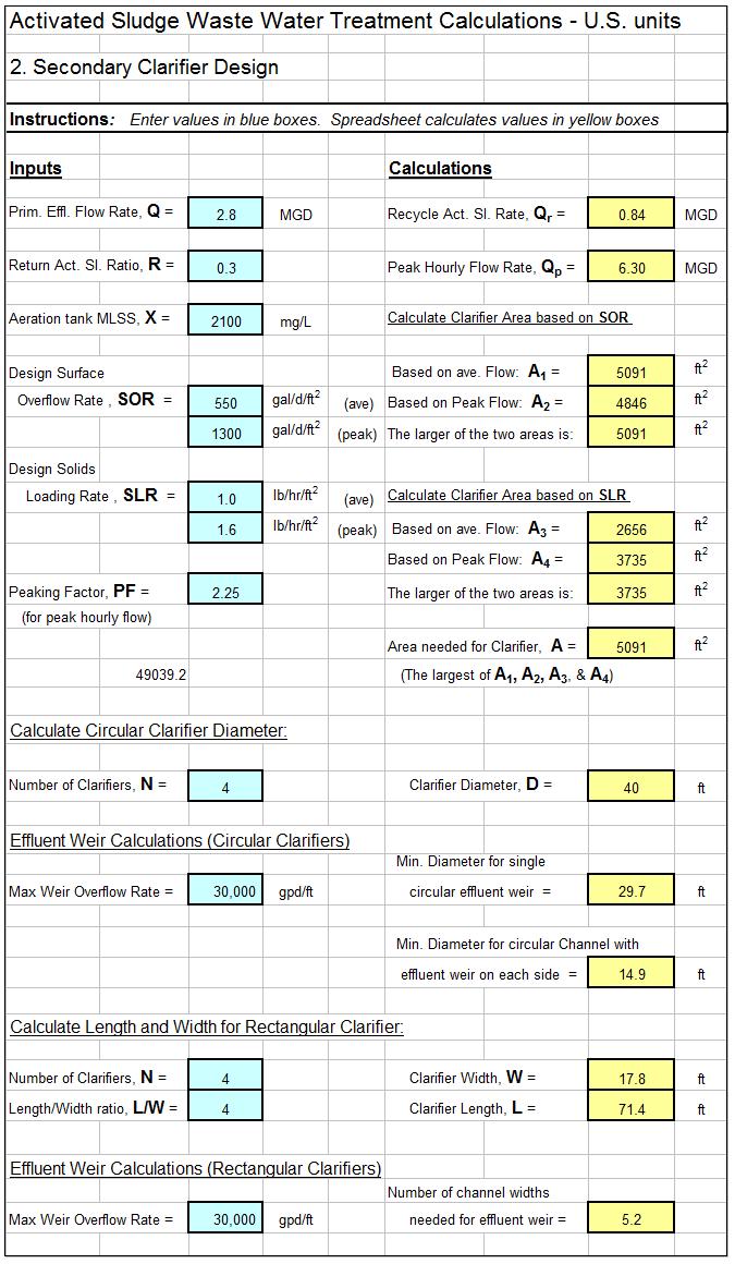
To calculate in English units all you need to know is basin flow in MGD overflow rate in gpmft 2 and clarifier diameter in ft.
. Calculate acceptable surface overflow rates 2. This configuration provides for maximum settling of solids toward the sludge pick-up. 1 Horizontal flow 2 solids contact and 3 inclined surface.
If the flow to the unit is 485 MGD what is the surface loading rate. Primary clarifier sizing shall be calculated for both flow conditions and the larger surface area derived shall be utilized. Is the secondary clarifier calculated weir overflow rate acceptable given the acceptable design is between 5000 to 15000 gpdft.
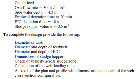
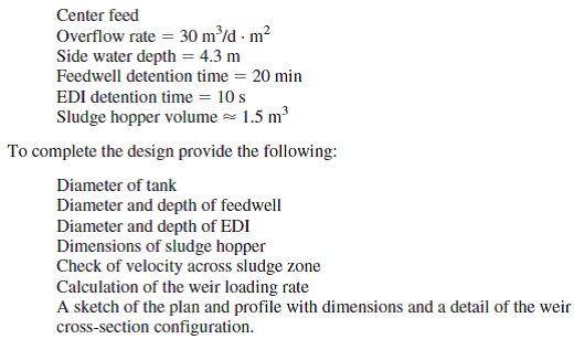
However anticipated bod removal for wastewater containing high quantities of industrial wastewater should be. Side water depth 43 m Feedwell detention time 20 minutes. The result of this calculation can be compared with design.
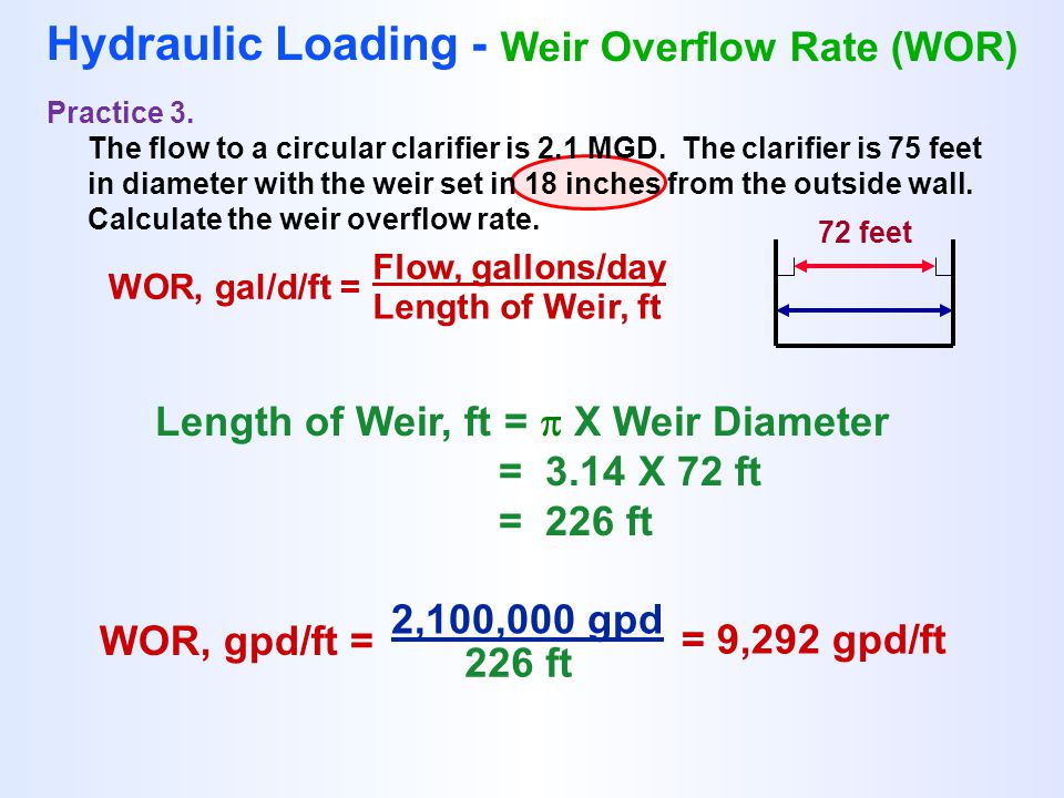
There is not enough data to calculate the weir overflow rate. Pounds per foot applied to the rotating sludge removal arm. Normally weir overflow rates of 10000 to 20000 gpdft are used in the design of a settling tank.
In rectangular clarifiers lengthwidth ratio is between 15 and 75 usually 3. The result of this calculation can be compared with design. Circular primary clarifiers are used to separate suspended solids from a liquid.
Calculate minimum required surface area and clarifier diameter 3. The weir overflow rate can be determined by. The water flow is evenly distributed and spirals down around the annulus of the clarifier by means of a specially designed baffle skirt.
By performing a series ofsettling tests atdifferent MLSS concentrationsseveral com-WhereVoand k are settling constantsbinations ofX and G values can be generatedoptimizing clarifier sizeand enhancing con-obtained from a series ofsettling testsAThe solids flux curve is then developed byfidence in the design process. Normally weir overflow rates of 10000 to 20000 gpdft 2 are used in the design of a settling tank. The clarifier vessel wall shall be fabricated of 14 structural steel grade ASTM designated carbon steel plates joined by arc welding with fillets of adequate section for the joint involved.
In the following table primary clarifiers design parameters values are established. The cost of construction material is cost must be considered to make a decision on calculated by multiplying weight of construction the number of tanks material by the cost per unit weight of table 2. For secondary clarifiers that follow an activated sludge system the solids loading rate should fall in the range of 12 to 30 pounds of solids per day per square foot of clarifier surface area.
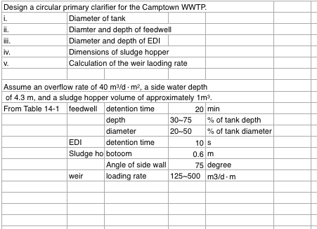
Diameter of tank Diameter and depth of feedwell Check of velocity across sludge zoon. Central feed water enters a circular well designed to distribute the flow equally in all directions D of feed well 15-20 of tank diameter Depth 1- 25m Velocity through the orificies on feed well 0075- 015 msec Inlet Structures continue entrance pipe suspended from bridge OR encased in concrete beneath the tank floor 12 13. All walls shall be continuous and watertight and shall be supported by structural reinforcing members where required.
What is the volume of water in the clarifier. Results of test problem 1 using computer programming input parameters vfr m3d 75708 tssin mgl 22000 tssout mgl 9900 output. Secondary Clarifier Design Fourche Creek WWTP 10 PurposeObjective Perform calculations necessary to design the new circular secondary clarifier for the Fourche Creek WWTP in Little Rock AR.
The result of this calculation can be compared with design. Clarifiers form part of the process known as sedimentation. X Flow or Volume x 834 Lbsgallon X Quantity Of Water The STUFF Is In Weight Of The Water X Pounds Equation 23.
To complete the design provide the following. Pounds Concentration Of STUFF In the Water Conc. A circular clarifier has a diameter of 150 ft.
Carbon steel grade A285 is chosen as Calculation of torque for a circular drive unit is the material of construction for the clarifier tank based on the simple cantilever beam-type based on its characteristic properties with a density equation with a uniform load W applied of 7850kgm3. PDF On Jan 1 2009 Nikolay Stojanov Voutchkov published Clarifier Design Find read and cite all the research you need on ResearchGate. Clarifier Loading Calculations Tank Volume MG X 24 Flow into Tank MGD Detention Time DT Flow gallonsday Surface Overflow Rate SOR Surface Area ft2 Weir Overflow Rate WOR Flow gallonsday Length of Weir ft Solids Loading Solids lbsday Surface Area ft2 But First Area and Volume Calculations Surface Area Calculations.
They are used extensively in the waste water treatment and water treatment industries but also in mining facilities reverse osmosis plants and paper and pulp plants to name a few industries. No it is higher than acceptable design values. A circular clarifier has a diameter of 40 ft and a depth of water of 25 ft.
MGD gpmft 2 1440 minday Minimum Required Area Tank Diameter 2 Clarifier Radius Pi R 2 Clarifier AreaClarifier Area Minimum Required Area Uncovered Area. Center feed Overflow rate 30 mdm². Normally weir overflow rates of 10000 to 20000 galdayft are used in the design of a settling tank.
Question 5 Design a circular clarifier for a flow rate of 8450 md. The circular peripheral flow clarifier offered by PCS operates with the water flow entering the system at the periphery. Size Energy Dissipating.
A properly designed primary clarifier should remove 30 to 35 of the influent bod. Depending on the textbook you reference you will see. In circular clarifiers the radiusheight is usually between 25 and 8.
Calculation of torque for a circular drive unit is based on the simple cantilevered beam type of equation with a uniform load L ft. Typically weir loading rates are. Typical Design Value Max 30 lbsdft2 22.
Calculation of Biosolids pumping total solids TS and BOD and SS removal. Volume gal 0785 x. Yes it is lower than acceptable design values.
In a circular clarifier it could be up to 10. Calculations are carried out and presented for comparison with experimental measurements of point velocities in a circular clarifier in operation at an. Weir overflow rate gpdft flow gpd weir length ft Next.
Wastewater Clarifier Performance
Wastewater Clarifier Performance
Solved Design A Circular Clarifier For A Flow Rate Of 8 450 M3 D Chegg Com

Circular Clarifiers

Volume And Surface Area Of A Cylinder Formulas Right Circular Cylinder Cylinder Formula Algebra Formulas Surface Area
Design A Circular Primary Clarifier For The Camptown Chegg Com
Solved Design A Circular Clarifier For A Flow Rate Of 34 560 M3 D Chegg Com
Clarifier Calculations Ppt Download
0 comments
Post a Comment